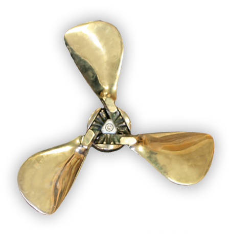
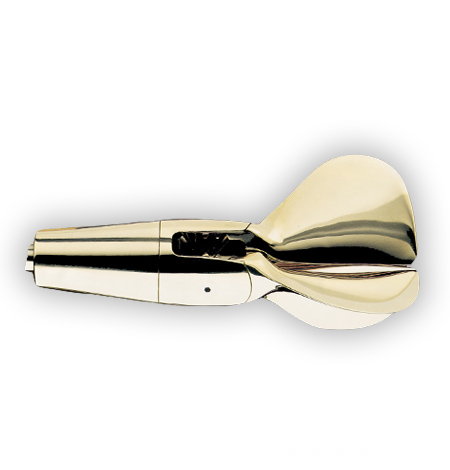
GORI 3-Blade Propeller
The GORI 3-blade folding propeller is available for installation on vessels with engines from around 10BHP to 300+BHP.
This unique design offers an “overdrive feature”, with 2 controlled pitch settings in forward and full reverse thrust. The “overdrive feature” gives lower engine RPM for the same cruising speed when in calm waters or motor-sailing.
The 3-blade propeller is available in diameters from 15” ~ 30+”, and pitch settings between 60% and 80% of the diameter. They are available in both LH and RH configurations for both saildrive and shaft installations.
The GORI 3-blade propeller won the “DAME” design award at the Meets on November 1994 and the “HISWA” award in December 1994. In November 1994 the German Magazine “Die Yacht” published results of independent tests carried out by the Technical University of Berlin. These results showed conclusively the advantages of the GORI 3-blade propeller.
Ahead: GORI was 11+% more efficient than 3-blade feathering props tested.
Astern: GORI was 6.5+% more efficient than 3-blade feathering props tested.
Sailing: Drag was reduced by nearly 50% compared to the 3-blade feathering propeller under test.
The German sailing magazine “Segeln” tested propeller drag at the German Naval Architecture Test Center in Potsdam and results show the GORI 3 Blade propeller had less drag than all the other makes of 2-blades & 3-blades (except the GORI Race) with 1.4 Newton.
Calculate Prop Size
3-Blade Standard Shaft
| Diameter | Pitch Range | Rotation | Shaft Dia. to ~ 1.125 | to ~ 30mm | Shaft Dia. 1.25 ~ 1.375 | 30mm ~ 35mm | Shaft Dia. 1.50 ~ 2.00 | 38mm ~ 50mm | Shaft Dia. 1.75 ~ 2.50 | 45mm ~ 60mm |
|---|---|---|---|---|---|---|
| 15 | 9 to 12 | RH ~ LH | ✔ | – | – | – |
| 16.5 | 10 to 13 | RH ~ LH | ✔ | – | – | – |
| 18 | 11 to 14 | RH ~ LH | ✔ | ✔ | – | – |
| 20 | 12 to 16 | RH ~ LH | – | ✔ | ✔ | – |
| 22 | 13 to 17 | RH ~ LH | – | ✔ | ✔ | ✔ |
| 24 | 15 to 19 | RH ~ LH | – | – | ✔ | ✔ |
| 26 | 16 to 21 | RH ~ LH | – | – | ✔ | ✔ |
| 28 | 17 to 23 | RH ~ LH | – | – | – | ✔ |
| 30 | 18 to 24 | RH ~ LH | – | – | – | ✔ |
3-Blade Saildrive
| Diameter | Pitch | Rotation |
|---|---|---|
| 15 | 9 to 12 | RH ~ LH |
| 16.5 | 10 to 13 | RH ~ LH |
| 18 | 11 to 14 | RH ~ LH |
| 19/20 | 12 to 16 | RH ~ LH |
GORI 3-Blade Measurement Table
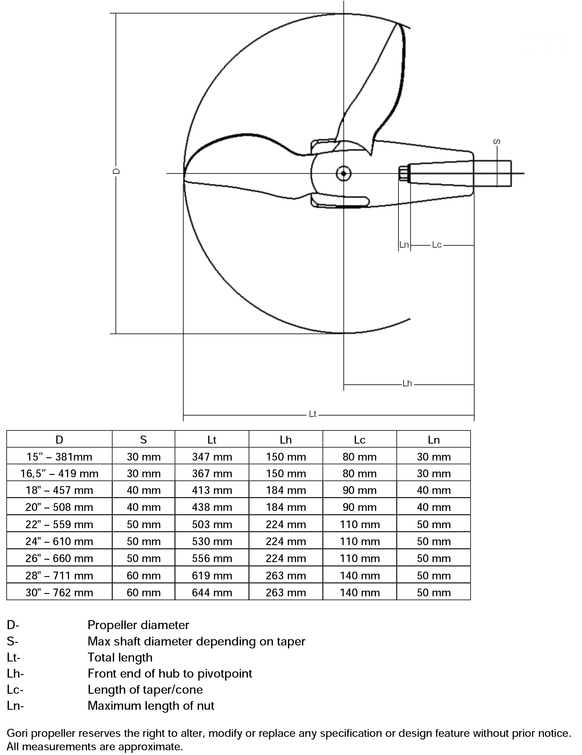
Propeller and Shaft Clearance Dimensions
Make note of the distances A through I below so that your propeller can fit with proper tip clearance.![]()
A. Shaft Diameter
B. Aft end of cutlass to start of taper/forward edge of hub
E. Shaft centerline to hull at forward edge of hub
F. Shaft centerline to hull at end of shaft thread
H. End of shaft to leading edge of rudder
I. Start of taper/forward edge of hub to rudder
Download Propeller and Shaft Clearance Form
Please read these instructions carefully before installing your new GORI propeller
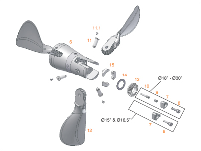
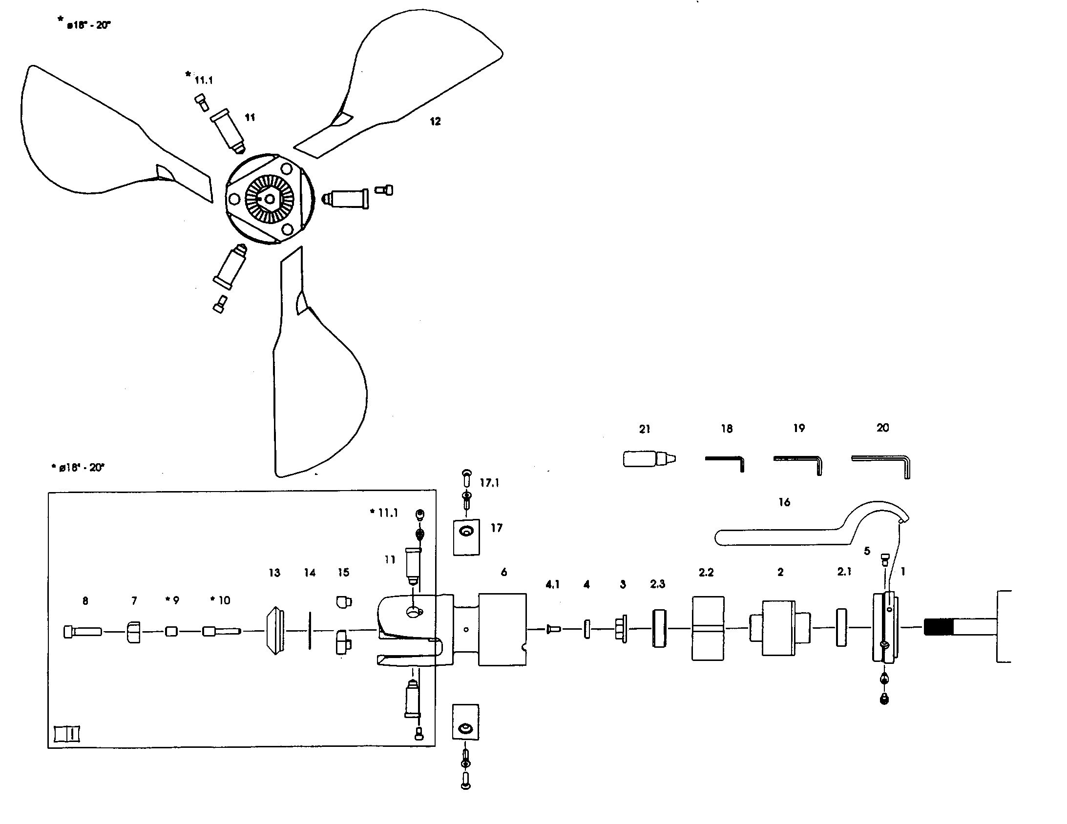
Parts List:
1. Retaining Cap
2. Inner Hub
2.1 Peek Bushing
2.2 Flexible Bushing
2.3 Peek Bushing
3. Nut
4. Washer for nut-locking bolt
4.1 Nut locking bolt
5. Locking bolts for retaining cap
6. Blade housing
7. Zinc anode
8. Fixing bolt for zinc anode
9. Threaded pin on 18-20 only
10. Fixing bolt for pins 18-20 only
11. Pins (3 x each)
11.1 Outside locking bolts for pins
12. Propeller blades (3 x each)
13. Gear Wheel
14. Spacer
15. Flexible Stops (3 x each)
16. C-Spanner
17. Zinc ring anode
17.1 Fixing bolts for zinc ring anode
18. Allen key 4mm
19. Allen key 5mm
20. Allen key 6mm
21. Locking glue / Loctite 243
Warning ~ do not remove the blades from the blade housing when installing or removing the propeller from the shaft!!!!
To remove blades – the center Fixing Bolt “MUST” be removed first!!!!
Installing the Propeller
The propeller is delivered assembled. This ensures that at the factory the propeller has been checked, and balanced prior to shipping.
Take apart the retaining cap (1). To do this … First remove the 3 x allen head bolts (item #5) holding the retaining cap (1) in place.
Now undo the retaining cap using the C-Spanner (16). The thread on the blade housing assembly (6), is a standard right to tight and left to loose. You may use a hammer with care, to tap the C-Spanner to get the retaining cap started as it is a firm, tight fit.
You will now have the retaining cap and blade housing assembly (6), (with blades installed) separate.
Check the shaft nut (3) & the nut-locking bolt (4.1) with the output shaft threads.
Remove the inner hub (2), flexible bushing (2.2), and PEEK bushings (2.1-2.3) from the blade housing (6).
Slide the retaining cap (1), PEEK bushing (2.1), inner hub (2), flexible bushing (2.2), and PEEK bushing (2.3) on to the saildrive shaft, matching the splines on the output shaft with those in the inner hub (2). Smear splines & shaft with waterproof lubricant.
Fit the nut (3), and tighten. Typically 72ft/lb. of torque for 1.00” dia. shaft.
It is very important to always use the Gori supplied propeller nut for the installation. An incorrect nut can lead to loss of the propeller, part of the propeller or cause an electrical connection between the propeller and the saildrive.
Smear locking glue (Loctite 243) on the thread of the nut-locking bolt (4.1). Place the washer (4) into the shaft hut and then thread the nut-locking bolt (4.1) using a 5mm allen key (19). Typically tighten to 10 ft/lbs of torque.
Slide the complete blade housing assembly (6 thru 17.1), onto the flexible bushing (2.2), so that the 2 x security cams slide into the grooves of the flexible bushing (2.2). Wet the bushing to allow it to slide in easily.
Continue to slide the blade housing onto the assembly until the thread of the retaining cap (1), and the blade housing (6) are touching. Smear a threads with waterproof lubricant.
Screw the retaining cap (1) RH or clockwise onto the blade housing assembly (6). Using the C-spanner (16) tighten until the 3 x holes in the retaining cap are aligned with the 3 x half circle cutouts in the blade housing assembly.
Now using the Loctite-243 (21), re-install the 3 allen head bolts (5) using the 5mm allen key (19), into the holes and tighten firmly.
Check that the blades will move freely from fwd to reverse and that the tip clearance with the hull is 10% of the blade diameter.
Removing the propeller
Warning ~ DO NOT remove the blades from the blade housing when removing the propeller from the saildrive leg.
First remove the 3 x allen head bolts (5), from the retaining cap
Now using the C-Spanner (16), undo the retaining cap so that it separates from the blade housing assembly (6). This is a right hand thread… simple right is tight…left is loose.
Carefully remove the blade housing assembly, by pulling off from the flexible bushing (2.2) and inner hub (2). These two items along with the bushings (2.1-2.3) will remain on the output shaft
Unscrew the nut-locking bolt (4.1) and also remove the washer (4) using a 5mm allen key (19).
Unscrew the shaft nut (3). It will be necessary to lock the output shaft when undoing the nut
Pull the inner hub (2), flexible bushing (2.20, end bushings (2.1 & 2.3), and retaining cap (1) off the output shaft.
Replacing the Aft Zinc
This should be done if more than 50% of the zinc (7), has been eroded away.
Undo the allen head bolt (8) and remove the old zinc (7) … if not gone completely.
Clean the propeller so as to ensure a clean strong bond with the new zinc.
Replace the zinc with new zinc, align the zinc with the end of the hub & the alignment hole with the pin in the end of the hub.
Use the new allen head bolt supplied … smear with loctite 243 also supplied, before re-installing the new bolt. Check that the blades will swing freely from fwd thru to reverse. If not and there are tolerance issues it may be necessary to realign or lightly file the sides of the zinc.
Replacing the Fwd Collar Zinc
This should be done if more than 50% of the zinc (17), has been eroded away.
First remove the 4 x allen-head bolts (17.1) and remove what is left of the zinc
Clean the surface of the propeller hub to ensure a good clean contact between the hub and the new zinc
Install the new zinc (17) using the Loctite 243 (supplied) on each of the 4 x allen-head bolts.
Replacing Flexible Stops
These can be replaced without removing the blades. Using a flat screw driver … pry out the old or worn Flexi-stops (15). Push or tap the new flexi-stops in place. It may be necessary to swivel the blades open and closed to obtain the best angle for re-installing the new ones. Remember they are flexible.
Removal of blades from the Blade Housing
To remove blades – the center Fixing Bolt “MUST” be removed first!!!! This must only be done when cleaning and a full service of the propeller is required.
NOTE: Blades are not removed for the installation and removal of the propeller
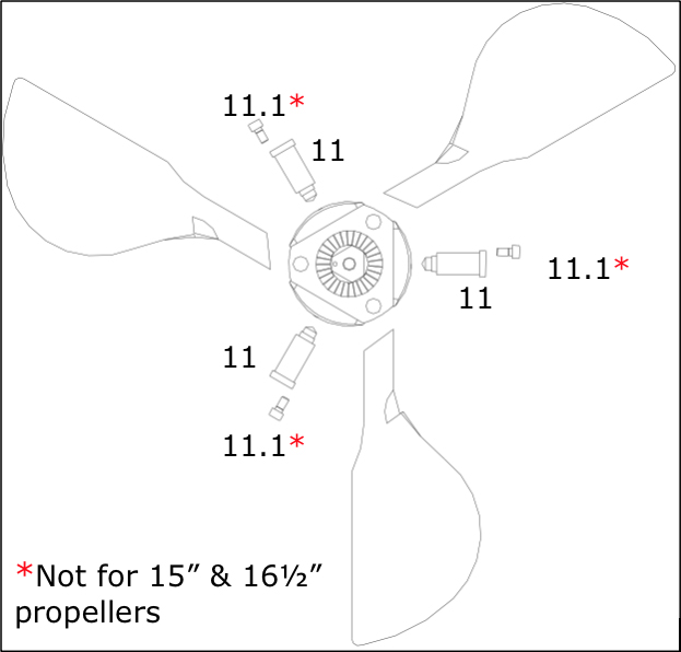
Remove the zinc centre bolt (8) and the zinc anode (7), using a 5mm allen key (19). On propellers 18.0” and larger it will also be necessary to remove the threaded pin (9) using a 6mm allen key (20) … then remove the fixing bolt (10) using a 5mm allen key (19).
Failure to remove all these pins(8-9-10) first, will result in damage to the internal threads of the blade pins (11).
Disassemble the blade pins (11 & 11.1) from the blade housing using a 6mm allen key (20). Note that blades, pins and the housing are matched and numbered. They should only be reassembled in the correct location … that is #1 – # 2 – # 3.
Remove the blades.
Remove the gear-wheel (13) and the spacer (14).
Remove the flexible stops (15) using either a flat blade screw driver or pliers.
When re-mounting the blades and gears to the housing it is important to apply loctite-243 to … blade pins (11 +11.1), lock pin (10), threaded pin (9), fixing bolt (8).
The lock bolt (10) and the fixing bolt (8) are the very last items to be reassembled.
Be sure that all components fit back together and that the blade pins (11) are located as before removal, as they are indexed inside the hub to lock bolts (10 +8).
Note:
If more than 50% of either of the zincs (7-17) has been eroded away they should be replaced.
If the gear wheel (13) has been damaged or worn…it should be replaced
If the flexible stops (15) have been damaged or worn…they must be replaced.
Warning:
– Do not start the engine while the boat is out of the water
– The prop may have sharp edges… be careful not to cut yourself
– Make sure the blades do not open or close suddenly and trap your fingers
– Stop the engine before diving or swimming in the vicinity of the boat
– Propeller blades can cause considerable damage when rotating … be careful.
– Do not remove fish nets, rope or similar from the prop with the engine running.
– Check that the prop works in both fwd and reverse before each trip. If any strange sounds or vibrations are noticed coming from the propeller stop the engine and investigate the reasons/solve the problem.
Download GORI 3 Blade Saildrive Installation Maintenance Instructions
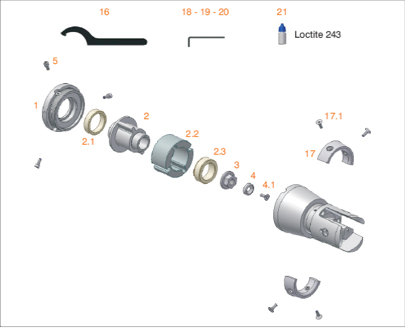
Please read these instructions carefully before installing your new GORI propeller
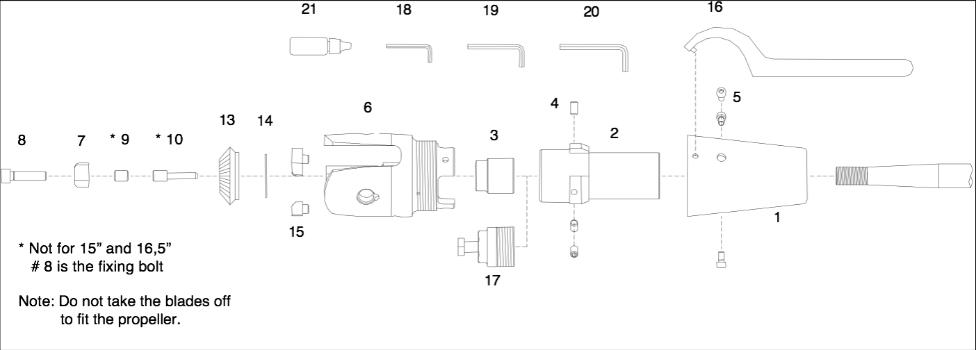
Parts List:
1. Jacket
2. Hub (Cone)
3. Shaft Nut
4. Allen Screws (3) for Locking Shaft Nut
5. Lock Bolts (3) for Jacket (item 1)
6. Blade Housing
7. Aft Zinc Anode
8. Fixing Bolt for Zinc
9. Threaded pin
10. Fixing bolt for Blade pins (Item11)
11. Blade Pins (3)
11.1. External Pin Locking Bolts
12. Propeller Blades (3)
13. Gear-Wheel
14. Spacer
15. Flexible Stops (3)
16. C – Spanner
17. Propeller Puller
18. Allen Key 4mm
19. Allen Key 5mm
20. Allen Key 6mm
21. Loctite (Blue)
Installing the Propeller
The propeller is delivered assembled. This ensures that at the factory the propeller has been checked, and balanced before shipping.
If your propeller has a fwd collar zinc installed, remove this first (22 + 23)
Take apart the jacket (1) from the blade housing (6).
First remove the 3 x allen head bolts (5) holding the jacket (1) in place.
If supplied with a fwd collar zinc remove this zinc first.
Now undo the jacket using the C-Spanner (16). The thread on the blade housing assembly is a standard right to tight and left to loose. You may use a hammer with care, to get the jacket started as it is a firm fit.
You will now have the jacket and blade housing (with blades installed) and the hub cone (2) separate.
Check the fit of the hub cone (2) onto the shaft. Adjust the key if necessary.
Check the shaft nut (3) with the shaft threads.
Slide the jacket (1) onto the shaft first. Now slide the hub cone (2) onto the shaft and tighten the shaft nut (3) very tightly. Typically up to 72ft/lbs of torque
Cover the allen screws (4) with Loctite-242 and tighten these dog point allen screws into the hub cone (2), locking the shaft nut(3), firmly in place. To do this you will need to rotate the jacket to line up an access hole with the allen screws (4).
Slide the blade housing assembly onto the hub cone (4), making sure that the tabs engage the hub cone. Push it fwd until you can start the thread of the jacket (1).
Tighten the jacket (1) to the blade housing assembly. Use the C-Spanner (16) to tighten and align the 3 threaded holes (5) with the holes in the jacket.
Now using Loctite-242, re-install the 3 allen head bolts (5) into the holes and tighten firmly.
Check that the blades will move freely from fwd to reverse.
Removing the propeller
Warning ~ do not remove the blades from the blade housing when removing the propeller from the shaft
First remove the Fwd split collar zinc, then the 3 x allen cap head bolts (5), from the jacket.
Now using the C-Spanner, place it on the stb side, & hammer down, unscrewing the jacket so that it separates from the blade housing and push it fwd on the shaft.
Carefully remove the blade housing assembly by pulling straight aft.
Undo the allen screws (4) to allow removal of the shaft nut (3). It is not necessary to remove them completely from the Hub cone (2).
Unscrew the shaft nut (3)
Install the bronze puller (17) into the hub cone (2). Thread it in all the way.
Tighten the large bolt in the centre of the puller (17) and this will draw the hub cone off of the shaft.
Replacing the Aft Zinc
This should be done if more then 50% of the zinc (7), has been eroded away.
Undo the allen head bolt (8) and remove the old zinc (7) … if not gone completely. Clean the contact area.
Replace the zinc with a new one … index the fwd end of zinc with the end of the hub pin to the zinc hole.
Use the new allen head bolt supplied … smear with loctite before re-installing the bolt.
Replacing the Fwd Collar Zinc
First remove the 4 x allen-head bolts and remove what is left of the zinc
Clean the surface of the propeller hub to ensure a good clean contact between the hub and the new zinc
Install the new zinc using the Loctite (supplied) on each of the 4 x allen-head bolts
Replacing Flexible Stops
These can be replaced without removing the blades.
Using a flat screw driver … pry out the old or worn Flexi-stops (15)
Push the new flexi-stops in place. It may be necessary to swivel the blades open and closed to obtain the best angle for re-installing the new ones. Use the blades to “push” home the stop into its location hole. Remember they are flexible.
Removal of blades from the Blade Housing !!!
This must only be done when cleaning and full service of the propeller is required.
Blades are not removed for the installation and removal of the propeller
Remove the centre bolt (8) and the zinc anode (7), using a 5mm allen key (19).
On propellers 18.0” and larger it will also be necessary to: remove the threaded pin (9) using a 6mm allen key … then remove the lock bolt (10) using a 5mm allen key.
Failure to remove these pins first will result in damage to the internal threads of the blade pins (11).
Disassemble the blade pins (11 & 11.1) from the blade housing using a 6mm allen key. Note that blades, pins and the housing are matched and numbered. They should only be reassembled in the correct location … that is #1 – # 2 – # 3.
Remove the blades.
Remove the gear-wheel (13) and the spacer (14).
Remove the flexible stops (15) using either a flat blade screw driver or pliers.
When re-mounting the blades and gears to the housing it is important to apply loctite-242 to … blade pins (11 +11.1), lock pin (10), threaded pin (9), fixing bolt (8).
The lock bolt (10) and the fixing bolt (8) are the very last items to be reassembled.
Be sure that all components fit back together and that the blade pins (11) are located as before removal as they are indexed inside the hub to lock bolts (10 +8).
Warning:
– Do not start the engine while the boat is out of the water
– The prop may have sharp edges… be careful not to cut yourself
– Make sure the blades do not open or close suddenly and trap your fingers
– Stop the engine before diving or swimming in the vicinity of the boat
– Propeller blades can cause considerable damage when rotating … be careful.
– Do not remove fish nets, rope or similar from the prop with the engine running.
– Check that the prop works in both fwd and reverse before each trip.
– If any strange sounds or vibrations are noticed coming from the propeller stop the engine and investigate the reasons/solve the problem.
Download GORI 3 Blade Standard Shaft Installation Maintenance Instructions
Would you like us to contact you to discuss GORI propellers without obligation?
If you are interested in our GORI products, we would like to send you further information.
Please fill out the form below and we will contact you immediately. Or feel free to call us at 401-847-7960